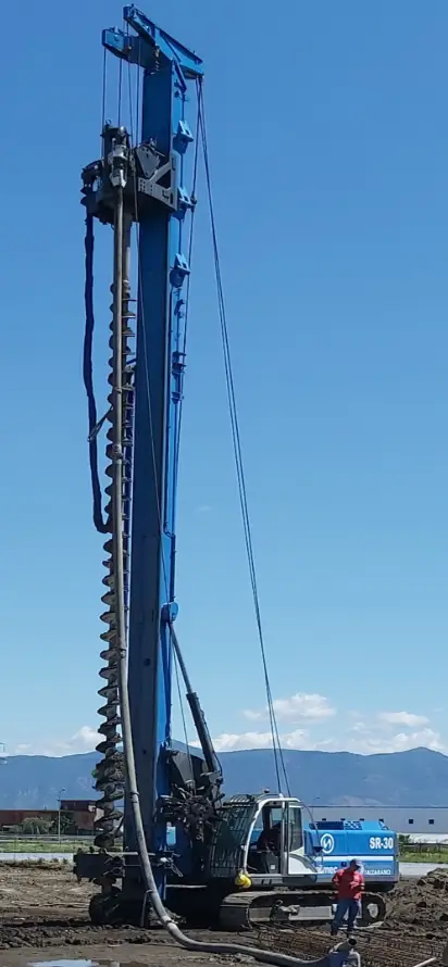
10” CFA SYSTEM
Measurement system for Continuous Flight Auger machines
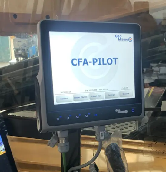
CFA measurement system 10'' is a logger device for the drilling and grouting parameters applied to the technology of continuos flight auger (CFA) device unit with a 10” touchscreen display.
The system allows to measure and store the following parameters
PERFORATION PHASE
- Perforation depth
- Propeller advance speed
- Pressure of the propeller rotation torque
- Pressure of the propeller rotation torque
- X and Y inclination mast
- Infeed Pressure (Optional)
- Torque CSP Pressure (Optional)
- Concrete Flow Measurement via Radio from the Pump (Optional)
- Connection with CAN-BUS drilling engine (Optional)
UPWELLING-JET PHASE
- Perforation depth
- Propeller up-rising speed
- Graph of the concrete pile profile
- Pumped concrete volume
- Concrete Flow rate
- X and Y inclination mast
- Pumped concrete pressure
- Graph of concrete Pressure
- Automatic up-rising
. 10” CFA SYSTEM user Interface is a 10 inch touchscreen display with high brightness and equipped with a USB port for the data download. By using the remote router connection the system allow to the client to control and watch the monitor from a remote pc or smartphone. It also give the opportunity to download the data from remote and, in case of need, we can support our customers with an immediate remote assistance. The system include also a GPS module with metric precision.
The connection to the in-field sensors is made possible through a multiple connector which allows for a fast disassembly and connection.
Automatic control of the rising of the auger dependent on the actual pumped concrete flow is operated by controlling an analogue output signal interfaced with the driller rising system of the drilling machine.
The Central Unit includes a software button to disable the depth measure when the auger is elongated or drawn back.
Data is stored into internal memory and then downloaded to a PC using a standard USB key. by using VISUAL-SGD software, the operator can carry out the statistical analysis of stored data during the operation, as well as other quality controls, including the printing of records with the typical graphs of each concrete pole so realized.
The parameters can be displayed on the customer's fleet management portal, where all the customer's devices along with their locations, acquired datasets, and a real-time telemetry dashboard can be viewed..
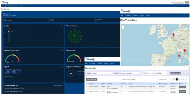
Thanks to VISUAL-SGD, it is possible to customize the printing configuration by modifying the display scales, the printing colours, etc. following the customer needs. Besides showing the records of the measurement values previously listed, the report of each drill rod identifies the Building Yard, the Rod Number, the Max. Depth, the Date, the Start and End Time, the Duration, the Total pumped Concrete Volume, and the extra-consumption with respect to the predefined hypothetical volume.
It is also possible to display and print a final report (e.g., for the current day) such as a list of the concrete poles carried out, including the main values for each operation as described above.
The sensors wiring system is composed of two connector boxes.
The first one is integrated to the rotary head; the depth sensor, the torque measurement sensor, the concrete pressure/volume sensor and the RPM sensor are connected to the first block.
A second connector box, which includes the protection circuit, is installed into the cabin; the antenna inclination sensor, the central unit, the automatic rising control circuitry, the optional remote connection unit and the Power supply are connected to this block too.
Main technical characteristics
- 10” touchscreen display
- USB slot used to download data stored
- Mechanical protection: IP65 (DIN40050)
- Power: 24 V dc (18-36V), 50 W
- Working temperature range: -20° C +60° C
- Connector oriented design
Info Request